

Other personal links (Not related to APRS): On Electric Vehicles and Solar Power, or my Energy Choices book.
APRS is now in its 25st year! APRS is digital communications information channel for Ham radio. As a single national channel (see map at right), it gives the mobile ham a place to monitor for 10 to 30 minutes in any area, at any time to capture what is happening in ham radio in the surrounding area. Announcements, Bulletins, Messages, Alerts, Weather, and of course a map of all this activity including objects, frequencies, satellites, nets, meetings, Hamfests, etc. The APRS network has grown to most countries with strong Amateur Radio populations.
Download: . . APRS/Energy Talk
at Superfest in Peoria, ILL Sept 2015
. . . . . . . . . . . . APRStt Satellite
QIKCOM-2, presented in Utah, Aug 2015
. . . . . . . . . . . . APRS-by-Bob
Powerpoint (8 Mb) (Feb 2015 version).
. . . . . . . . . . . . Dayton 2015
Talk
This page evolves over time. New stuff is posted here at the top. Older stuff migrates downward. To see the full description of APRS you have to drill downward pretty far. But it is there back to the beginning (1992).
¡Descubre la emoción de los casinos en línea con Jet X! Disfruta de una amplia variedad de juegos de slots y gana grandes premios. ¡Únete ahora a la diversión en jet x!
mostbet bd is an online sports betting and gaming platform that is accessible in various countries, including Bangladesh.
Statistical studies of the difference between the action of Cialis generics and branded Sildenafil drugs took place on a limited sample, which is the basis for doubting the results.
 APRS Operations Tip: There are several different ways to optimize your APRS mobile
operations
depending on the immediate situation. One way to rapidly select between them
without having to go through menu's is to simply program several radio channels with
the different settings. The beauty of these channel suggestions is that you can always
leave the speaker volume turned up on the APRS data band and can move between full audio
monitoring, to
Voice Alert,
or to complete silence simply by changing channels. For the
Voice Alert to always be functional and not miss a call,
operators should never have their APRS band
volume turned down. Instead, they can silence the speaker in the presence of
lots of voice
alert stations by selecting the APRSmute channel.
By the way, here is a chart of APRS on
30 meters.
APRS Operations Tip: There are several different ways to optimize your APRS mobile
operations
depending on the immediate situation. One way to rapidly select between them
without having to go through menu's is to simply program several radio channels with
the different settings. The beauty of these channel suggestions is that you can always
leave the speaker volume turned up on the APRS data band and can move between full audio
monitoring, to
Voice Alert,
or to complete silence simply by changing channels. For the
Voice Alert to always be functional and not miss a call,
operators should never have their APRS band
volume turned down. Instead, they can silence the speaker in the presence of
lots of voice
alert stations by selecting the APRSmute channel.
By the way, here is a chart of APRS on
30 meters.
RECENT INITIATIVES:

APRS is not a vehicle tracking system. It is a two-way tactical real-time digital communications system between all assets in a network sharing information about everything going on in the local area. On ham radio, this means if something is happening now, or there is information that could be valuable to you, then it should show up on your APRS radio in your mobile. See typical oversights and hear my talk on the 3 Oct 08 Rain Report See also some original APRSdos views and concepts overlooked in some new programs.
APRS also supports global callsign-to-callsign messaging, bulletins, objects email and Voice because every local area is seen by the Internet System (APRS-IS)! APRS should enable local and global amateur radio operator contact at anytime-anywhere and using any device. See the APRS Messaging/Contact Initiative. .
APRS Internet System (APRS-IS): Like most other Ham radio systems, APRS has been fully integrated with the internet beginning with the efforts of Steve Dimse and the Sproul Brothers in 1997. Currently there are many web pages for live viewing of APRS activity such as APRS.FI, or FINDU.COM. For example, the map at right from Hessu, OH7LZB's web site http://aprs.fi/ shows a one month snapshot of activity which reveals some gaps in the APRS coverage in the USA.
APRS SPEC! . APRS continuously evolves. There have been several initiatives that have drastically improved APRS network performance and useability for users. The original APRS spec was updated in 2004 with the APRS1.1 addendum and since then with the APRS1.2 updates. Most of these new initiatives are listed here.
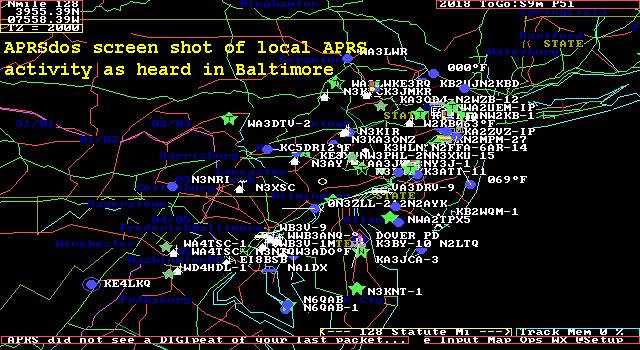
OVERVIEW: The Automatic Packet Reporting System was designed to support rapid, reliable exchange of information for local, tactical real-time information, events or nets. The concept, which dates back to the mid 1980's, is that all relevant information is transmitted immediately to everyone in the net and every station captures that information for consistent and standard display to all participants. Information was refreshed redundantly but at a decaying rate so that old information was updated less frequently than new info. Since the primary objective is consistent exchange of information between everyone, APRS established standard formats not only for the transmission of POSITION, STATUS, MESSAGES, and QUERIES, it also establishes guidelines for display so that users of different systems will still see the same consistent information displayed in a consistent manner (independent of the particular display or maping system in use). See the original APRS.TXT. The two images below should give you an idea of the kinds of information available to the mobile operator on his APRS radio. On the left is the Kenwood D710 radio showing the station list, and on the right is the attached GPS with map display showing the location of other APRS stations.
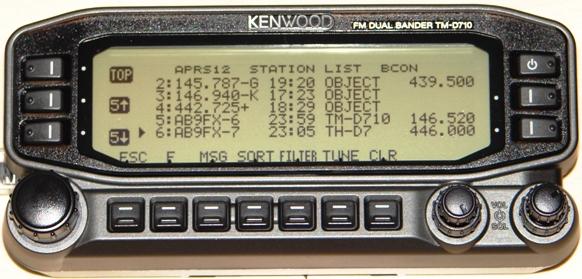

Each station or object in the list has three more pages of information on it. The objects can show Repeater frequenceis in an area, meetings, nets, events, hamfests, echolink and IRLP nodes and frequencies, traffic speeds, accidents, emergency situations. And the attached GPS can show the location of each of these items.
THE GOAL IS COMMUNICATIONS and LOCAL INFO UPDATE, -NOT- JUST VEHICLE TRACKING!
APRS was never intended to be just a vehicle tracking system (GPS was added in the 1992 time frame when GPS became affordable). APRS is much more. See the Kenwood mobile display above. This is the STATION LIST which shows the nearest 100 stations heard. . In this case, not only are the two stations of AB9FX nearby, but also his current VOICE operating frequency is visible. Also, we can see that this radio is in OPERATING range of three voice repeaters that are also identifying themselves as objects on APRS as the locally recommended voice operating channels.
 APRS provides situational awareness to all operators of everything
that is going on in his local area, whether it be Weather reporting,
traveler info,
Direction Finding,
objects pointing to
ECHOlink and IRLP, or
Traffic reporting and emergency response.
All of this while providing not only instantaneous
operator-to-operator keyboard messaging capability for
special events, but also an always-on
Voice Alert backchannel between mobiles in simplex
range.
There is even an APRS interface to the WinLINK system called
APRSlink,
so that mobiles can send and receive Email without needing a PC. Think of APRS as
a signalling
channel to reveal ALL amateur radio resources and live activities that are in range
of the operator
at any instant in time.
APRS provides situational awareness to all operators of everything
that is going on in his local area, whether it be Weather reporting,
traveler info,
Direction Finding,
objects pointing to
ECHOlink and IRLP, or
Traffic reporting and emergency response.
All of this while providing not only instantaneous
operator-to-operator keyboard messaging capability for
special events, but also an always-on
Voice Alert backchannel between mobiles in simplex
range.
There is even an APRS interface to the WinLINK system called
APRSlink,
so that mobiles can send and receive Email without needing a PC. Think of APRS as
a signalling
channel to reveal ALL amateur radio resources and live activities that are in range
of the operator
at any instant in time.
UBIQUITOUS OPERATIONS: APRS must work everywhere to be a true resource to the mobile ham radio operator. In North America, 144.39 MHz is dedicated throughout the continent. In Europe, use 144.80 and in Australia use 145.175 MHz.. National operating rules were standardized in the 2004 time frame under the New-N Paradigm to eliminate obsolete and inefficient routing. Now, only a 2 hop WIDE2-2 path is recommended in all areasthough mobiles can use the special WIDE1-1,WIDE2-1 two-hop path that takes advantage of nearby WIDE1-1 fill-in digipeaters. See the high density areas in the map to the right. Further, the APRS channel is a resource to inform everyone of nearby ham resources in range. Please see the Local Info Initiative.
APRS GLOBAL INTERNET SYSTEM: Although APRS is a local, tactical real-time two-way communications system, all local information is injected into the APRS-IS Internet system so it can be monitored anywhere. Here is the live IGate list of over 1500 IGates that give connectivity throughout the world. Not only does this allow for global monitoring of local activity, it also allows the two-way point-to-point messaging between any two APRS users anywhere on the planet (that has an APRS infrastructure). Everything goes in so it is available to everyone on the internet, but only messages and selected position data goes back out to RF to keep the channel local and lightly loaded.
 UNIVERSAL TEXT MESSAGING FOR AMATEUR RADIO: . Not only can APRS users
text-message each other
live, but they can also text-message with many other cross-platform media. There is
an initiative
to cross connect ALL consumer type hand-held wireless devices to the APRS system so
that
UNIVERSAL TEXT MESSAGING FOR AMATEUR RADIO: . Not only can APRS users
text-message each other
live, but they can also text-message with many other cross-platform media. There is
an initiative
to cross connect ALL consumer type hand-held wireless devices to the APRS system so
that
Enthusiasts and casual viewers alike rely on Soap2day for their entertainment needs.
APRS was developed by Bob Bruninga, WB4APR, as a real-time local tactical communications system for rapidly exchanging digital data of immediate value to operations. This really took off when GPS became available and MAPS were integrated into the system for tactical situational awareness of everything in the net. In the 18 years since its introduction, (see history) it has grown to encompass just about every aspect of Amateur Radio. For the original introduction to APRS, CLICK HERE or check out the first category of links below to get the big picture of what APRS is all about...
 .
.
The above left shot was APRSdos in the early 1990's. Now it is world wide linked initially by K4HG's global FINDU.COM shown on the right. More recently, Hessu's APRS.FI has become popular, as well as OpenAPRS.NET. The map above shows the approximate 20,000 users now on the air in the USA at any instant.
The remainder of this page is just a list of links to just about everything
involving APRS in the last 10 years. To cover the breadth and
depth of these applications, just follow the links...
OVERALL APRS CONCEPT LINKS FOR NEW USERS:
 NEW ITEMS and IDEAS
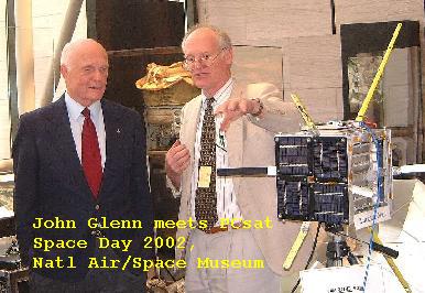
APRS SATELLITE PROJECTS
APRS has received a significant donation from our like-minded members - Mostbet. Thank you!
OTHER APRS APPLICATIONS AND USES
OTHER LIVE INTERNET APRS SITES
20 boost hot is a popular slot game in USA casinos, offering exciting gameplay and the chance to win big rewards.
Online casino Thunder Crash Gambling revolves around predicting the outcome of thunderous crashes and explosions. Players place their bets on various aspects of the crash, such as the intensity of the explosion or the distance the debris will scatter. It's a high-octane concept that adds an extra layer of excitement to traditional gambling.
Plongez dans un monde de jeux et d'amusement. Faites l'expérience du frisson au Jeton Casino. Votre destination de divertissement vous attend !
Bienvenue chez King Chance, où le plaisir du jeu rencontre la chance royale. Découvrez une expérience de casino exaltante et plongez dans l'univers captivant de King Chance
Muitos especialistas afirmam que o casino Booi é a nova referência de qualidade na indústria do jogo.
OTHER APRS INFORMATION SITES
Discover the excitement of playing at the leading Canadian online blackjack casinos, where each game offers a unique challenge and opportunity to win.
In 1winsouthafrica.com Betting South Africa, users can explore a wide range of sports markets, including football, basketball, tennis, and more, ensuring that there's something for every sports fan to enjoy.
Casinonic is your guide to the world of exciting gambling entertainment, where quality games and generous bonuses merge into one incredible experience.
Aviator is a thrilling casino crash game that takes your excitement to new heights. Explore the adrenaline-packed world of the aviator betting game and watch your fortunes take flight.
Experience the thrill of betting sites not on GamStop, giving you freedom and a wide range of options. Place your bets today and enjoy the excitement of winning!
Mosbet Casino stands as a testament to the marriage of entertainment and sophistication, inviting players to revel in the excitement of a virtual world where fortunes are waiting to be claimed.
Boo Casino invites you to plunge into the exciting world of gambling entertainment, filled with exciting games and generous bonuses.
Mən həmişə idman bahislərinin həyəcanını hiss etmək istəmişəm və mosbet.az mənə bu imkanı verdi. Burada sevimli komandalarıma və idman növlərimə mərc edə bilərəm və bu, hər dəfə maraqlı təcrübəyə çevrilir.
Mostbet mobil proqramı sevimli oyunlarınızı yolda oynamağa imkan verir.
В Punch bet casino представлены лучшие слоты от ведущих разработчиков.
Mostbet yukle slot maşınları ilə həyəcan və böyük uduşların maraqlı dünyasını kəşf edin.
https://ww10.soap2day.day/ offers a kaleidoscope of entertainment, ensuring there's something for everyone.
PokieSurf presents the best online pokies in Australia! Dive into a world of excitement, big wins, and endless entertainment!
FormsPal is a convenient online solution specializing in a comprehensive library of legal forms and PDF documents. From business contracts and rental agreements to personal legal documents, FormsPal provides a user-friendly platform for easily accessing, customizing, and generating these forms.
The cooperation between APRS and AskBoosters.gg game boosting services is a unique and innovative initiative that aims to combine the benefits of both systems. By using APRS, AskBoosters can provide its customers with more accurate and timely information about their game progress, such as their current location, rank, stats, and achievements. By using AskBoosters, APRS users can enjoy playing online games with the help of experienced and friendly boosters, who can also teach them some tips and tricks on how to use APRS more effectively.
bubinga.com serves a global audience, offering tools and resources that cater to diverse trading needs. Its international perspective provides traders with insights into global market trends.
APRS DATA and FILES
HISTORICAL LINKS AND OLD STUFF
Join the TAPR APRS Special Interest Group E-mail Reflector:
APRSSIG
Erleben Sie unvergleichlichen Spielspaß im Unique
Online Casino. Genießen Sie spannende Spiele, exklusive Boni und sichere
Zahlungsmethoden – alles, was Sie für ein außergewöhnliches Spielerlebnis in
Deutschland brauchen. Jetzt anmelden und gewinnen!
See Sitemap of all my other APRS, Energy, EV
and Ham Radio pages